деформационных швов
Компания Дьюмарк производит и поставляет профили для всех типов деформационных швов для любых зданий и сооружений. Более 1000 типоразмеров позволяют подобрать профиль под любые условия эксплуатации.
Гидроизоляция
Различные решения для гидроизоляции деформационных и технологических (рабочих) швов.
декоративные элементы
Производство противопожарных барьеров и защитных элементов конструкций зданий
мостов
Профили и материалы для деформационных швов в мостовых сооружениях
Dewmark Flex
cords
шнуры
Бентонитовые шнуры Дьюмарк Бент
Шнуры на основе природного бентонита натрия служат для гидроизоляции заглубленных сооружений
резина
Шнуры из гидрофильной резины Дьюмарк Ватерфил
Созданные на основе EPDM и гидрофильного полимера, набухающие при контакте с водой, шнуры создают активные барьеры против воды под давлением
Защитные и антивандальные уголки призваны защитить углы колонн и стен от механических воздействий. В зависимости от материала из которого они выполнены могут обладать ярким демпфирующим эффектом.
Используя различные материалы исполнения вкупе с широкой цветовой гаммой мы можем произвести и подобрать уголок под любой интерьер.
Напольные плинтусы призваны обеспечить переход от пола к стене без образования щелей и канавок. Мы производим несколько типов плинтусов:
- Алюминиевые прямые - декоративные плинтусы
- Промышленные алюминиевые плинтусы с кабель-каналом
- Легкие промышленные гибкие ПВХ Плинтусы
- Промышленные плинтусы из ПВХ для помещений с агрессивными средами
Dewmark Concrete SG 63
-
LoadsLoads (EN)  330.80 kB
DrawingsПрисылайте запрос на info@dewmark-joint.com
Сертификаты1853-CPR-108 Dewmark steel EN 1.24 MB
-
Calculation of base plates and loads
 CalculateSelection result
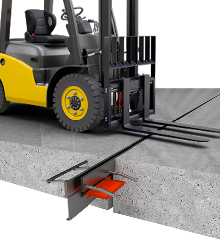 Application of support plates. Load bearing calculations.
The use of base plates was the development of the evolution of Omega profiles for concreting work joints. Due to the quick-detachable casing, adjacent to the body of the base plate, and an increase in the area of contact between the base plate and concrete, it was possible to increase the load-bearing loads of the floor.
The support plates carry and transfer the load between two adjacent sections of the concrete floor, that is, the loaded equipment moves along the finished floor without causing stress in the concrete slab. A concrete slab usually has only about 50% of its bearing capacity at the edges, so the dowels support the slab at the edges and help to support and transfer weight from one slab to another, allowing the slabs to bend slightly, gently transferring the load along its surface.
Calculation of the bearing capacity of the base plates is given in the British methodological manual TR34 ver. 4 clause 6.5.
The force on the shear of the base plate is determined by the formula:
Where - cross-sectional area of the base plate
- steel yield strength
Bearing / bending load on the base plate:
Where

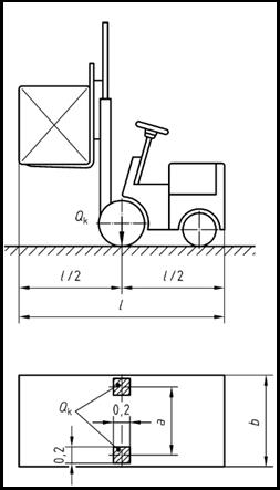
- distance of load application from the concrete surface; with a symmetrical arrangement, this is equivalent to half the seam opening (see fig.)
(constant)
= concrete strength =
- base plate width
- base plate thickness
- the strength of the steel of the base plate (taken equal to the yield strength of the steel)
Loader category by sizeCategory , m , m , m G1 0,85 1,00 2,60 G2 0,95 1,10 3,00 G3 1,00 1,20 3,30 G4 1,20 1,40 4,00 G5 1,50 1,90 4,60 G6 1,80 2,30 5,10
Loader category Weight Limit, kN Lifting capacity, kN Axle load*, kN Wheel load*, kN Distributed load per m2, (kN/м2) Wheel-to-surface contact area, mm mm Loader G1 31 10 26 12,5 12,5 200х200 Loader G2 46 15 40 15 15 200х200 Loader G3 69 25 63 31,5 17,5 200х200 Loader G4 100 40 90 45 20 200х200 Loader G5 150 60 140 70 20 200х200 Loader G6 190 80 170 85 20 200х200 * - shock-free
-
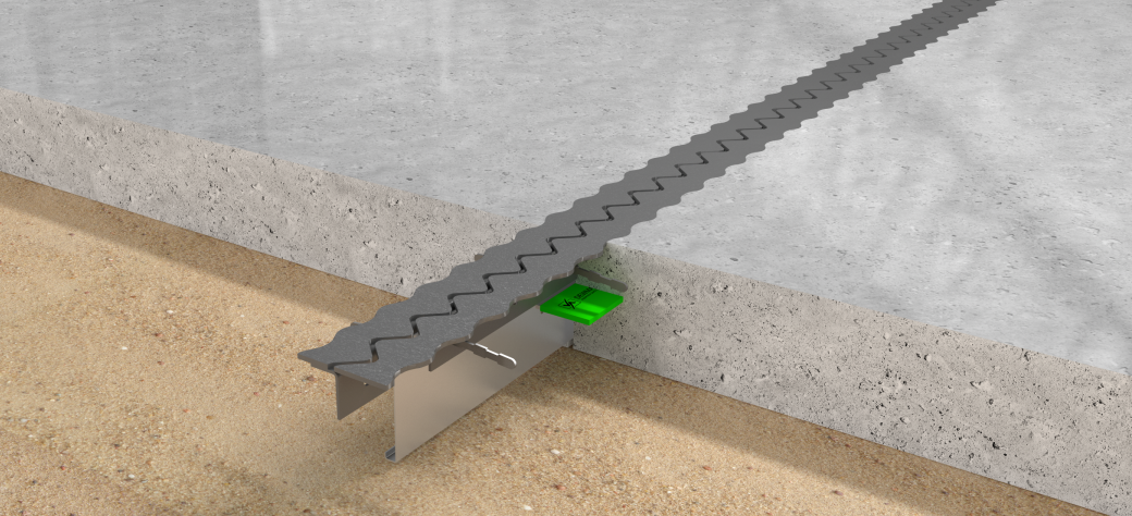
Description
Profile for concrete joints with flat sinus top plates. Due to its geometry, it allows impact-free passage through the expansion gap, even with steel wheels, in-creasing the performance of the concrete floor while reducing vibration and noise during the expansion gap.
The profiles are designed for loads according to TR 34 4th edition and Eurocode 2: EN 1992-1-1.
Together with the load transfer system, it allows two adjacent slabs to be in one plane even with a gap open-ing of 20 mm.
Produced with two types of top plates to choose from: straight side edges (type SG 63) and corrugated side edg-es to increase the resistance of floors to dynamic loads (type SG 63-ZZ)
It perfectly reinforces the edges of the concrete on both sides of the shrinkage joint and serves as a reliable system for transferring loads during storage and when the equipment passes through the joints.
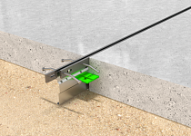
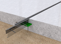
Components (specification)1 Steel flat sinus plates (2 types)1 2 Steel guide brackets 3 Profile body 4 Load transfer dowel (3 types)2 5 Dowel steel casing 6 Riveted fasteners 7 Welded screw 8 Nut 9 Dowel mounting bracket 10 Steel rivet 11 Fixing screw 1 It is available in two types of top plates:
- SG 63 - with straight side edges;
- SG 63-ZZ - with wavy sides.

